
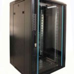
 FREE STANDING CABINETS
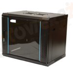 WALL MOUNTED CABINETS
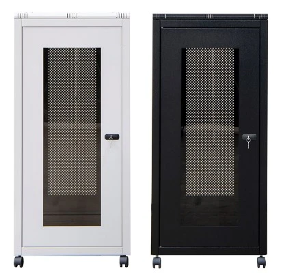
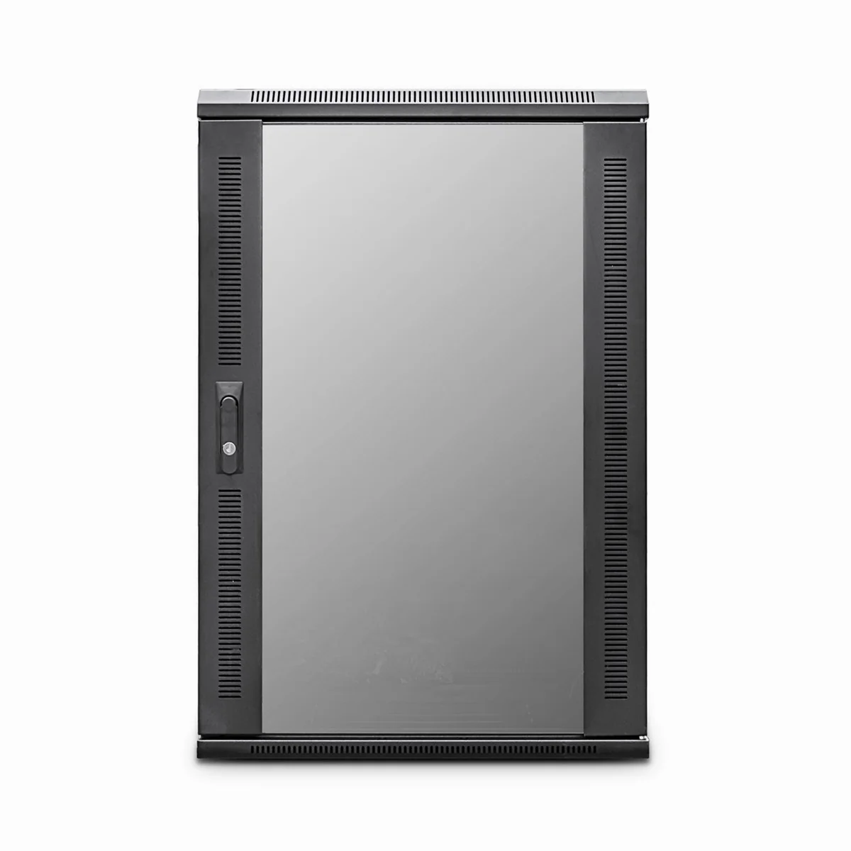
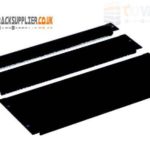 Blanking panel
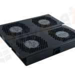 fan units
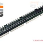 PATCH PANEL
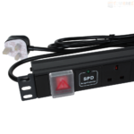 Power Distribution Unit
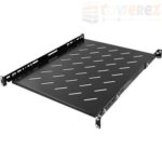 SHELVES
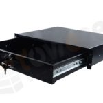 RACK DRAWER
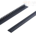 TOWEREZ RAILS
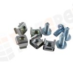 CAGE & NUTS

How to Plan a 22U Server Cabinet Layout: UK Guide to U-Space, Equipment Order and Cable Management


A good 22U server cabinet layout places heavy equipment low, leaves room for airflow and maintenance, separates power from data where practical, and reserves enough U-space for future growth. Start with an equipment list, convert each item into rack units, check depth and weight, then arrange the cabinet from the bottom upwards before installing anything.
What is a 22U server cabinet?
A 22U cabinet is a rack enclosure with 22 vertical rack units, or “U”, of mounting space. One U is 44.45 mm high, so 22U represents 977.9 mm of nominal mounting height. The available space may be less in practice because of the cabinet’s base, roof, cable entry areas, vertical rails and equipment clearances.
Most cabinets use the standard 19-inch rack format. However, a device being 19-inch compatible does not automatically mean it will fit every enclosure. Check the cabinet’s usable depth, front and rear rail adjustment, maximum equipment depth, door clearance and permitted load before buying equipment or rails.
A 22U cabinet is often suitable for a small office, branch site, laboratory, security system, network room or edge installation. It can accommodate a mixture of switches, patch panels, a firewall, shelves, a UPS and a small server, but the final capacity depends on the depth, weight and cooling requirements of each device.
Begin with a rack equipment schedule
The most reliable way to plan a 22U server cabinet layout is to create a simple rack schedule. Do this before choosing the installation order. Record the following for every item:
- Equipment name, model and purpose.
- Required height in U, including any manufacturer-supplied rails or trays.
- Depth, including rear connectors, cable bend radius and power leads.
- Weight and whether the item needs two-post, four-post or shelf support.
- Power draw, plug type and whether it needs a dedicated or redundant feed.
- Heat output or cooling guidance from the manufacturer.
- Front and rear access requirements.
- Network, fibre, serial, USB and management connections.
List fixed-height items first. A patch panel may occupy 1U, a switch may occupy 1U or 2U, and a server may occupy between 1U and several U. A tower server, non-rack appliance or desktop UPS may need a rack shelf rather than direct mounting. Treat the shelf and its load rating as part of the design, not as an afterthought.
Add the U values together and compare the result with 22U. Do not plan to fill every unit. A practical design normally reserves space for a replacement device, a second patch panel, a larger UPS, cable access or a future network switch. The exact allowance depends on the project, but leaving several free U is safer than designing a cabinet that has no room to change.
Recommended 22U server cabinet layout from bottom to top
There is no universal order for every site, but a bottom-to-top arrangement can provide a useful starting point:
- Bottom: UPS or heaviest supported equipment. Place the heaviest item as low as possible to lower the cabinet’s centre of gravity. If a UPS is not rack-mountable, use a properly rated fixed shelf or a manufacturer-approved floor arrangement. Confirm that the cabinet floor and shelf can support it.
- Lower section: servers and storage. Rack servers and storage arrays are often heavy and may have rear power and data connections. Keep enough rear clearance for airflow, rails and service access.
- Middle section: switches, firewalls and other active network devices. This position is convenient for patching and maintenance. It can also help keep short horizontal links between patch panels and switches.
- Upper-middle section: patch panels and fibre enclosures. Patch panels are easier to reach when they are near the technician’s normal working height. Keep fibre trays and bend-radius guides close to fibre termination points.
- Top section: light accessories and cable management. Horizontal managers, brush panels and lightweight accessories can occupy the upper area. Do not place heavy equipment at the top simply because the space is available.
This order is a guideline rather than a rule. For example, a switch may need to sit immediately below a patch panel to keep copper patch leads short, while a manufacturer may require a particular UPS orientation or clearance. Document any deliberate exception in the rack elevation.
How to allocate U-space correctly
Draw the cabinet as 22 numbered rows, with U1 at the bottom and U22 at the top. Place each item into its planned position and show blank spaces clearly. This rack elevation becomes an installation plan and a useful service document.
When measuring equipment, include more than the metal chassis. Allow for rail kits, mounting ears, cable managers, airflow gaps and devices that may extend behind the rear rails. Some equipment has front-to-back airflow and requires unobstructed intake or exhaust space. Others use side-to-side airflow and may be unsuitable for a crowded cabinet with blocked side panels.
Use cage nuts, bolts and mounting screws that match the cabinet rails. Mark the front and rear rail positions before lifting equipment. For heavier devices, install rails or a shelf first and use two people where the manufacturer recommends it. Never rely on a single pair of front screws to support equipment that is designed to rest on rear rails or a shelf.
Manage weight, stability and access
Weight distribution is a key part of a safe 22U server cabinet layout. Put the heaviest devices near the base, keep the load centred between the rails and avoid concentrating equipment on one side. Check the cabinet’s static and rolling load ratings, especially if it will be moved after installation.
Secure a floor-standing cabinet to the floor or wall where appropriate, following the enclosure manufacturer’s instructions. Lock or remove castors when the cabinet is in its final position. Keep doors, removable side panels and rear doors clear enough to open fully. Measure the route into the room, including lifts, doorways and thresholds, before delivery.
Leave a safe working area in front and behind the cabinet. If the cabinet is installed against a wall, confirm that rear service access is not required or select equipment and cable methods that can be maintained from the front. A neat cabinet that cannot be serviced is not a successful design.
Plan airflow and temperature control
Airflow should be considered at the same time as equipment order. Many rack devices draw cool air through the front and discharge warm air at the rear, so avoid installing blanking plates, cable bundles or shelves that obstruct the intended path. Fit blanking panels over unused front spaces when appropriate to reduce recirculation inside the cabinet.
Check the cooling needs of servers, storage, PoE switches and UPS systems. A compact cabinet can accumulate heat quickly when several active devices are installed together. The room may need mechanical cooling or improved ventilation, but the cabinet should still maintain the manufacturer’s front-to-back airflow path.
Do not assume that a fan tray solves every thermal problem. A fan can improve air movement but may also add noise, dust and power consumption. Follow the equipment and cabinet instructions, monitor temperature where practical, and investigate rising temperatures rather than simply adding more fans.
Power distribution and PDU placement
Include power in the initial layout rather than routing it after the data cables. A rack-mounted power distribution unit, or PDU, is commonly fitted vertically at the rear or horizontally in a 1U position. Choose a model with suitable socket types, cable length, current rating, input connector and monitoring features.
Keep the PDU accessible without blocking device fans or rear service areas. If equipment has dual power supplies, consider separate power paths or PDUs where the site’s electrical design supports this. Redundant power supplies do not create redundancy if both are connected to the same failed source.
Use the correct UK plug, protective device and electrical installation arrangements. A qualified electrician should handle fixed wiring, circuits and any work that falls under applicable electrical requirements. Label both ends of power leads and avoid daisy-chaining extension blocks or PDUs unless the manufacturers and site rules explicitly permit the arrangement.
Allow enough slack to unplug a device without pulling on another connector, but do not coil long power leads tightly in front of ventilation openings. Route power leads along the cabinet sides or dedicated rear paths and keep them away from sharp edges.
Cable management for a clean 22U server cabinet layout
Good cable management reduces troubleshooting time and prevents accidental disconnection. Separate cable types by function where practical: copper data, fibre, management cables and power. Use vertical managers, horizontal managers, brush panels and rear cable rings to control routes without compressing the cables.
Use sensible patching routes
For copper links, place the switch close enough to the patch panel to keep patch leads short, but leave room to replace either device. Avoid crossing a large bundle diagonally across the rear of the cabinet. Use side routes and consistent bend directions instead.
Fibre requires particular care. Follow the minimum bend radius specified for the cable and connector system, use suitable fibre management hardware, and avoid tight hook-and-loop straps. Never force a fibre lead around a corner or allow its weight to hang from a connector.
Label, document and test
Label both ends of every permanent link with a consistent scheme. The label should identify the patch-panel port and destination, not merely the cable type. Keep a port map showing switch port, patch-panel port, outlet or device, VLAN or service where relevant, and test result.
Use hook-and-loop straps rather than over-tightened plastic ties for bundles that may need future changes. Group cables by destination, but leave enough slack for equipment removal and for the cabinet’s front or rear door to close. Test copper and fibre links after installation and record faults before the cabinet is closed.
Example 22U server cabinet layout
The following example illustrates the planning method. It is not a substitute for checking the dimensions and requirements of the actual equipment.
| Position | Equipment | Planning reason |
|---|---|---|
| U1–U2 | Rack UPS | Heavy equipment kept low; confirm cabinet and rail rating. |
| U3–U5 | Server or storage chassis | Lower position supports weight and leaves rear service space. |
| U6 | Blanking panel or cable management | Maintains airflow or provides a deliberate service gap. |
| U7–U8 | Network switch and firewall | Convenient for patching and administration. |
| U9 | Copper patch panel | Short, orderly links to the switch below. |
| U10 | Fibre enclosure | Close to fibre management and protected from sharp bends. |
| U11–U14 | Reserved growth space | Allows for a future switch, appliance or cable work. |
| U15–U22 | Light accessories and planned expansion | Use only after checking access, airflow and weight. |
In this example, the PDU would normally be mounted at the rear, subject to the cabinet design. The blank U-space is intentional: it provides flexibility and avoids forcing future equipment into an unsuitable position.
Installation and commissioning checklist
- Confirm the cabinet dimensions, rail spacing, depth and load rating.
- Verify every device’s U-height, weight, mounting kit and airflow direction.
- Check delivery access, final location, earthing and cabinet anchoring requirements.
- Install the cabinet level and secure it according to the manufacturer’s instructions.
- Fit the UPS, shelves, rails, PDUs and heavy devices before lighter equipment.
- Install blanking panels and cable managers where shown on the rack elevation.
- Route and label power, copper, fibre and management cables separately where practical.
- Check connector strain, bend radius, door clearance and fan openings.
- Test network links, power failover and monitoring before handover.
- Photograph the completed cabinet and store the final rack elevation and port schedule.
Key takeaways
- Start a 22U server cabinet layout with an equipment schedule, not with the cabinet itself.
- Place heavy devices low and keep the centre of gravity stable.
- Reserve U-space for growth, cable access and maintenance.
- Keep airflow paths clear and follow each manufacturer’s cooling guidance.
- Plan PDUs and cable routes before connecting equipment.
- Label, test and document every connection so the cabinet remains serviceable.
Frequently asked questions
How much equipment can fit in a 22U server cabinet?
The answer depends on the U-height, depth, weight, power and cooling requirements of the equipment. Add the rack units of all devices, then reserve space for cable management, maintenance and future growth. A cabinet should not be filled solely because 22U is available.
Where should a UPS go in a 22U cabinet?
Place a rack-mount UPS low in the cabinet because it is usually heavy. A non-rack UPS should sit on a manufacturer-approved, load-rated shelf or in an approved floor position. Check the UPS ventilation, service access and cabinet load rating before installation.
Should a patch panel be above or below a network switch?
Either arrangement can work. Put the patch panel and switch close together to reduce patch-lead length, then choose the order that gives the best access, airflow and cable route. Record the chosen positions in the rack elevation.
How can I improve cable management in a small server cabinet?
Use vertical and horizontal managers, label both ends of every cable, separate power from data where practical, protect fibre bend radius and use hook-and-loop straps. Leave serviceable slack without allowing bundles to block fans or doors.
{“@context”:”https://schema.org”,”@type”:”FAQPage”,”mainEntity”:[{“@type”:”Question”,”name”:”How much equipment can fit in a 22U server cabinet?”,”acceptedAnswer”:{“@type”:”Answer”,”text”:”The answer depends on the U-height, depth, weight, power and cooling requirements of the equipment. Add the rack units of all devices, then reserve space for cable management, maintenance and future growth. A cabinet should not be filled solely because 22U is available.”}},{“@type”:”Question”,”name”:”Where should a UPS go in a 22U cabinet?”,”acceptedAnswer”:{“@type”:”Answer”,”text”:”Place a rack-mount UPS low in the cabinet because it is usually heavy. A non-rack UPS should sit on a manufacturer-approved, load-rated shelf or in an approved floor position. Check the UPS ventilation, service access and cabinet load rating before installation.”}},{“@type”:”Question”,”name”:”Should a patch panel be above or below a network switch?”,”acceptedAnswer”:{“@type”:”Answer”,”text”:”Either arrangement can work. Put the patch panel and switch close together to reduce patch-lead length, then choose the order that gives the best access, airflow and cable route. Record the chosen positions in the rack elevation.”}},{“@type”:”Question”,”name”:”How can I improve cable management in a small server cabinet?”,”acceptedAnswer”:{“@type”:”Answer”,”text”:”Use vertical and horizontal managers, label both ends of every cable, separate power from data where practical, protect fibre bend radius and use hook-and-loop straps. Leave serviceable slack without allowing bundles to block fans or doors.”}}]}