
 FREE STANDING CABINETS
 WALL MOUNTED CABINETS


 Blanking panel
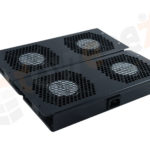 fan units
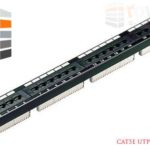 PATCH PANEL
 Power Distribution Unit
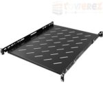 SHELVES
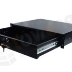 RACK DRAWER
 TOWEREZ RAILS
 CAGE & NUTS

Server Rack Earthing Requirements in the UK: Bonding, BS 7671 and Best Practice


In brief: server rack earthing requirements UK practice normally require every exposed conductive part of a rack and its associated metallic equipment to be connected to a reliable protective bonding system. The installation should comply with the applicable requirements of BS 7671, equipment instructions and relevant ICT bonding guidance, with continuity verified and documented by a competent person. A rack should never rely solely on painted frame joints, mounting rails or incidental contact through equipment fixings.
What does earthing a server rack mean?
Earthing and bonding are related but distinct concepts. Earthing connects an electrical installation or equipment to the general mass of earth through the installation’s protective system. Bonding connects exposed or extraneous conductive parts together so that, under fault conditions, dangerous potential differences are limited and protective devices can operate as intended.
For a typical UK server cabinet, the objective is to create a dependable low-impedance path between the rack’s metalwork, the protective conductors supplying equipment and the building’s earthing and bonding arrangement. This may include the rack frame, doors, removable side panels, roof panels, cable management, vertical mounting rails and metallic accessories where they can become energised or form part of the intended bonding network.
The exact arrangement depends on the supply system, rack construction, power distribution units, building infrastructure, electromagnetic compatibility requirements and the recommendations of the equipment manufacturers. It should therefore be designed as part of the complete electrical installation rather than treated as an optional cable added after the rack is installed.
Server rack earthing requirements UK: the main principles
1. Connect the rack to the protective earthing system
A rack containing mains-powered equipment should be connected to the installation protective conductor or to an appropriately designed protective bonding network. The connection should terminate at a designated earth or bonding point on the rack and be secured against loosening, corrosion and accidental removal.
The protective conductor arrangement must be suitable for the installation and fault conditions. Conductor size, route, mechanical protection and disconnection requirements are design matters governed by the applicable rules in BS 7671 and the characteristics of the circuit. There is no universal cable size that is correct for every server cabinet.
2. Bond accessible metalwork
Doors and removable panels can lose electrical continuity through hinges, powder coating, anodising or loose mechanical contact. Where continuity is required, use purpose-designed flexible bonding straps or links connected to dedicated rack earth points. The straps should allow the door or panel to open fully without being stretched or damaged.
Do not assume that a hinge, cage nut, mounting screw or painted metal-to-metal joint provides a permanent protective connection. Where a manufacturer supplies bonding hardware, use it in accordance with the installation instructions. If a connection passes through a coated surface, use an approved earth stud, bonding washer or other listed method that provides reliable contact without causing avoidable corrosion.
3. Bond associated metallic systems where required
Metallic cable trays, trunking, overhead containment, busbar systems, raised-floor components and adjacent cabinets may need to be bonded as part of the wider installation. The requirement depends on their electrical characteristics, accessibility, location and how the installation is designed. A rack should not be considered in isolation when it is installed in a data room or equipment hall.
4. Maintain continuity after every change
Adding a new PDU, cable management arm, patch panel, shelf, fan unit or replacement door can alter the intended bonding path. The completed installation should be checked after construction and again following significant modifications. Cable labels and rack documentation should identify the earth point and any intentional bonding links.
How BS 7671 applies to server cabinets
BS 7671 is the principal UK standard for the design, erection and verification of low-voltage electrical installations. It provides the framework for protective measures, protective conductors, automatic disconnection, earthing arrangements, inspection and testing. It does not replace the manufacturer’s instructions for a particular rack or IT system, and it should be used alongside the standards relevant to the project.
In practice, the designer or electrical contractor should consider:
- the earthing arrangement of the premises, such as TN or TT where applicable;
- the protective conductor serving each rack PDU or fixed item of equipment;
- fault-current paths and the operation of protective devices;
- the classification and accessibility of exposed conductive parts;
- mechanical protection and routing of protective conductors;
- segregation from data and communications cables where required;
- inspection, testing and certification of the completed work; and
- any special requirements for UPS systems, generators, isolated supplies or power-conditioning equipment.
Where the rack forms part of an ICT installation, BS EN 50310 may also be relevant for bonding networks and earthing practices supporting information and communication technology equipment. Other project standards can apply to telecoms rooms, data centres, lightning protection, fire safety and electromagnetic compatibility. The responsible designer should confirm which documents govern the particular installation.
Rack earth bar, bonding cable and connection methods
Many cabinets include a factory-fitted earth bar or threaded bonding points. These provide convenient connection locations, but their presence does not automatically prove that every removable metal part is bonded. Check the manufacturer’s drawings and identify which parts are electrically continuous and which require links.
A robust arrangement commonly includes:
- a primary protective bonding connection from the rack to the building or room earthing system;
- short, secure links from the earth bar to doors and removable panels where needed;
- bonding of metallic accessories that could become exposed conductive parts;
- correctly earthed rack PDUs and fixed electrical equipment; and
- clear labelling so that the connection is not removed during maintenance.
Use conductors and terminals with suitable current-carrying capacity, fault withstand, flexibility and mechanical protection. Shorter, direct connections generally reduce impedance, but the best route must also comply with segregation, access and installation constraints. Do not substitute a thin signal reference wire for a protective conductor, and do not use a data cable shield as the sole safety earth unless a specific engineered design and applicable standard permit it.
Protective earthing versus functional and EMC bonding
Server installations often need both safety bonding and a stable reference for electromagnetic compatibility. These objectives overlap, but they are not interchangeable.
Protective earthing and bonding are safety functions. They provide a fault-current path and help prevent accessible metalwork from remaining at a dangerous voltage. They must be designed and verified under the electrical installation requirements.
Functional or EMC bonding can reduce noise, shield interference and improve the performance of high-speed digital equipment. It may involve wide, short bonding straps, cabinet-to-cabinet connections, screened containment or a room bonding network. An EMC strap must not be assumed to replace the protective conductor unless it is designed and rated for that purpose.
In high-density rooms, the electrical designer and ICT or facilities engineer should coordinate the protective earthing, signal reference and bonding network. Poorly planned parallel paths can create unwanted circulating currents, while inadequate bonding can increase touch-voltage and interference risks.
Installation checklist for a UK server rack
- Review the design. Confirm the supply arrangement, protective device, rack location, room bonding infrastructure and manufacturer requirements.
- Inspect the cabinet. Locate the designated earth terminal or bar and identify doors, panels and accessories that need bonding links.
- Install the primary connection. Use an appropriately selected protective conductor with secure, accessible terminations and suitable mechanical protection.
- Bond removable parts. Fit flexible straps where hinges or painted joints do not provide verified continuity.
- Check adjacent metalwork. Assess containment, raised-floor components, neighbouring cabinets and other accessible conductive systems.
- Protect and label the connection. Prevent abrasion, sharp bends, accidental disconnection and unauthorised removal.
- Test the finished work. Carry out the inspections and electrical tests required for the installation, recording results and any limitations.
- Update records. Keep drawings, photographs, test results and maintenance instructions with the rack documentation.
Inspection and testing
Testing should be performed by a suitably competent person using calibrated equipment and methods appropriate to the installation. The test scope will depend on whether the work is a new circuit, an alteration, a rack bonding modification or part of a larger data-centre project.
Relevant checks may include visual inspection, protective conductor continuity, bonding continuity, polarity where applicable, earth fault loop or other verification appropriate to the supply, and functional checks of connected equipment. Testing a cabinet by touching a meter probe to a random painted surface is not a reliable substitute for checking the intended earth points and individual bonding links.
Record the identification of the rack, test method, measured results, instrument details, date, person responsible and any restrictions. If a rack is supplied through a UPS, power distribution system or unusual earthing arrangement, ensure the testing method is compatible with that system and does not create a hazard or damage equipment.
Common mistakes to avoid
| Common mistake | Why it matters | Better practice |
|---|---|---|
| Relying on rack mounting bolts | Paint, corrosion or looseness can interrupt continuity. | Use the designated earth terminal and dedicated bonding links. |
| Bonding only the main frame | Doors and panels may remain electrically isolated. | Check and bond removable conductive parts where required. |
| Choosing a cable size by habit | Fault conditions and installation methods differ. | Specify the conductor from the design and applicable requirements. |
| Using a data shield as the safety earth | Shielding is not automatically a protective conductor. | Provide a correctly designed protective connection. |
| Ignoring later modifications | New equipment or panels can interrupt the bonding scheme. | Reinspect and retest after significant changes. |
| Leaving earth points inaccessible | Maintenance becomes difficult and accidental disconnection more likely. | Keep connections identifiable, protected and maintainable. |
Who should design and certify the work?
Rack bonding is part of an electrical installation and should be designed, installed or verified by a person with suitable competence for the work. A facilities team may install manufacturer-provided links under a controlled procedure, but alterations to circuits, protective conductors or the building earthing system require appropriate electrical expertise.
For commercial premises, the duty holder should also consider the Electricity at Work Regulations, site procedures, risk assessments and maintenance controls. Building regulations, client specifications, insurer requirements or a data-centre standard may impose additional obligations. When requirements conflict or the installation is unusual, obtain a project-specific design review rather than relying on generic online advice.
Key takeaways
- Server rack earthing requirements UK installations depend on the complete electrical and ICT design, not just the cabinet.
- Connect the rack to a suitable protective earthing or bonding system through a designated, secure connection.
- Verify doors, panels and accessories instead of assuming that hinges, paint or mounting hardware provide continuity.
- Keep protective earthing separate from assumptions about functional, signal or EMC bonding.
- Apply BS 7671 together with manufacturer instructions and relevant ICT bonding guidance.
- Inspect, test, record and retest the arrangement after significant modifications.
Frequently asked questions
Does every server rack need a separate earth cable?
A rack containing mains-powered equipment needs a reliable connection to the installation’s protective earthing and bonding system. Whether it needs a separate cable from the rack to a room earth bar depends on the designed arrangement, the rack’s existing protective connection and the applicable requirements. Do not assume that a separate cable is unnecessary merely because equipment power leads have earth contacts.
Should server rack doors be bonded?
Doors should be bonded where their hinges or other contact points do not provide verified, dependable continuity and where they form part of the accessible conductive enclosure. Flexible bonding straps connected to designated points are a common solution. Follow the cabinet manufacturer’s instructions and verify the completed connection.
What size earth cable is required for a server cabinet in the UK?
There is no single size suitable for every cabinet. The conductor must be selected from the electrical design, fault conditions, protective device, installation method, mechanical risks and relevant standards. The rack manufacturer may specify a minimum, but that specification should not override the requirements of the complete installation.
Is BS 7671 enough for a data-centre rack?
BS 7671 is the key standard for the low-voltage electrical installation, but a data-centre or ICT project may also require guidance such as BS EN 50310, equipment instructions and client or facility standards. The applicable documents should be identified during design so that safety, EMC and operational requirements are coordinated.
How is rack earthing tested?
A competent person checks the intended connections visually and verifies protective conductor or bonding continuity with suitable test equipment. The broader test schedule depends on the electrical work and supply arrangement. Results should be recorded, and testing should be repeated after significant alterations that could affect continuity.
{“@context”:”https://schema.org”,”@type”:”FAQPage”,”mainEntity”:[{“@type”:”Question”,”name”:”Does every server rack need a separate earth cable?”,”acceptedAnswer”:{“@type”:”Answer”,”text”:”A rack containing mains-powered equipment needs a reliable connection to the installation’s protective earthing and bonding system. Whether it needs a separate cable from the rack to a room earth bar depends on the designed arrangement, the rack’s existing protective connection and the applicable requirements. Do not assume that a separate cable is unnecessary merely because equipment power leads have earth contacts.”}},{“@type”:”Question”,”name”:”Should server rack doors be bonded?”,”acceptedAnswer”:{“@type”:”Answer”,”text”:”Doors should be bonded where their hinges or other contact points do not provide verified, dependable continuity and where they form part of the accessible conductive enclosure. Flexible bonding straps connected to designated points are a common solution. Follow the cabinet manufacturer’s instructions and verify the completed connection.”}},{“@type”:”Question”,”name”:”What size earth cable is required for a server cabinet in the UK?”,”acceptedAnswer”:{“@type”:”Answer”,”text”:”There is no single size suitable for every cabinet. The conductor must be selected from the electrical design, fault conditions, protective device, installation method, mechanical risks and relevant standards. The rack manufacturer may specify a minimum, but that specification should not override the requirements of the complete installation.”}},{“@type”:”Question”,”name”:”Is BS 7671 enough for a data-centre rack?”,”acceptedAnswer”:{“@type”:”Answer”,”text”:”BS 7671 is the key standard for the low-voltage electrical installation, but a data-centre or ICT project may also require guidance such as BS EN 50310, equipment instructions and client or facility standards. The applicable documents should be identified during design so that safety, EMC and operational requirements are coordinated.”}},{“@type”:”Question”,”name”:”How is rack earthing tested?”,”acceptedAnswer”:{“@type”:”Answer”,”text”:”A competent person checks the intended connections visually and verifies protective conductor or bonding continuity with suitable test equipment. The broader test schedule depends on the electrical work and supply arrangement. Results should be recorded, and testing should be repeated after significant alterations that could affect continuity.”}}]}